WARNING
Make sure the whole control station is not energized before touching or starting your exercise!
If you have been performing previous experiments this could be the right moment to introduce another component of control cabinets: the contactor. In this experiment, you will rework previous installation but introducing a contactor as if you were to power up an electric motor.
Objective
Learn how does the contactor works and to install it along with the emergency stop button and its signaling pilot light.
Material
Multimeter
AC/DC power supply. Input 120V AC and output 24V DC, 1A (at least)
Push button (green )
Push button (red)
Pilot light (green). 24V DC
Pilot light (red). 24V DC
Pilot light (yellow) or buzzer. 24V DC
Encapsulated relay 24V DC with contacts for 8A 250V
Contactor. 25V DC coil with power contacts for up to 30 A
Emergency stop button
Bulb light. AC
What to do
For this exercise a contactor is to be introduced. The role of a contactor is to power equipments demanding high voltage and that could represent a danger for operators. The contactor is similar to an encapsulated relay: it has a coil too. A contactor also have two type of contacts: auxiliary and power contacts. The auxiliary contancts are to be used for low voltage and the power contacts for hugh voltage.
In this exercise an AC light bulb is to be used as a high voltage equipment.
Follow the same steps as for LE 05
Connect the emergency stop button on the (+) DC wire (before any of the rungs)
Set on the power supply
Use the following ladder diagram:
 |
| Ladder diagram for contactor installation |
The whole circuit should turn off when the emergency button is depressed
Check for continuity if needed
How to do it
For this exercise the same setup developed for LE 05 is to be used. Details shall be omitted but refer to LE 05 for more information.
Step 1. Identification of contactor
There are several models and here three of the most common brands are presented.
 |
| Example contactors from three different manufacturers.Notice that all of these have NO contacts. |
These components have two type of contacts: ones called power contacts used for high voltage connections required by electric motors for example, and auxiliary contacts used for low voltage connections such as pilot lights or other type of alarms.
 |
| Parts of a Siemens contactor. This component has a 24V DC coil, one NO and one NC contact. The power contacts are indicated as L1, L2, L3 and T1, T2, T3. |
Step 2. Emergency pilot light (yellow) connection
As the emergency stop button is depressed a yellow pilot light should turn on to visually indicate that an emergency has occurred and that an action has to be taken. This is a visual alarm. This pilot light is to be in series with the emergency stop button while the NO contact is in parallel with it.
| Yellow pilot light used for emergency alarm |
Step 3. Connecting the contactor
Step 4. Energizing the loop
In order to power the loop you should activate the circuit breaker to the ON position with the lever upl and the green indicator being shown.
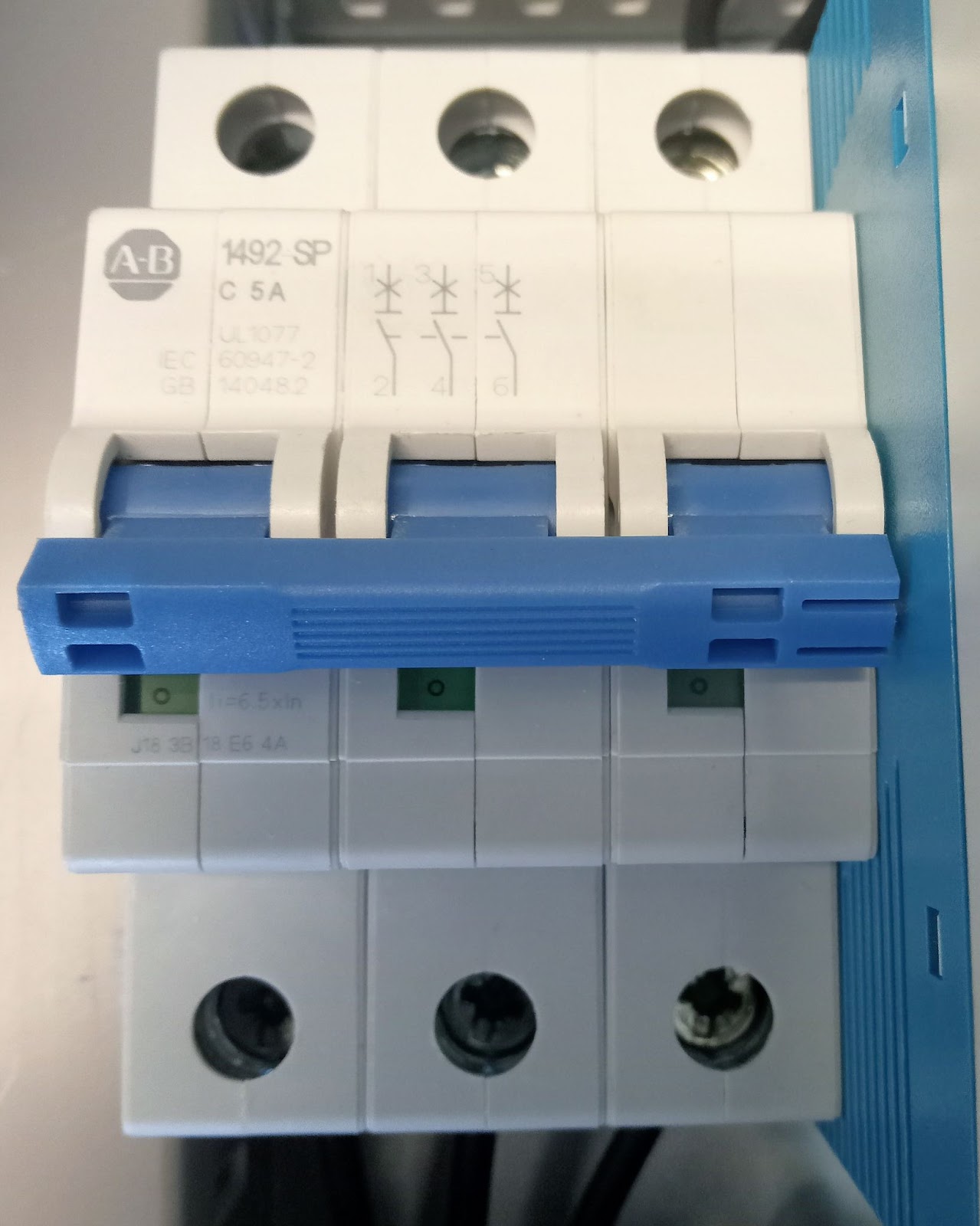 |
| Thermal circuit breaker |
Step 4. Using the buttons
If your connection was right then as the loop was powered, nothing should happen and only the green pilot light should turn on, indicating that everything is OK. However, when you push the start button the following should occur (in this order):
- the encapsulated relay coil is energized
- the encapsulated relay NO contacts close and the NC contacts open
- the green pilot light turns off
- the contactor coil is energized
- the contactor NO contacts close and the NC contacts open
- the red pilot light is turned on
- the AC bulb light also turns on
If you had a pump connected instead of the AC bulb light it should start pumping liquid.
If you need to restore power to the system the emergency stop button needs to be unlatched first. Depressed down and swirl it to the right to release the button to its unlatched state. The system could be started again if the start button were depressed and the green pilot litght is turn on again indicating safety.
Step 5. Continuity and DC voltage test
Check for continuity at every contact and for 24V DC using the multimeter. Since you are using a power source for 24V DC you should get a reading not far from this value.
Any question? Write in the comments and I shall try to help.
Other stuff of interest
- LE01 - AC and DC voltage measurement and continuity test
- LE 02 - Start and stop push button installation 24V DC
- LE 03 - Turn on/off an 24V DC pilot light with a push button
- LE 04 - Latch contact with encapsulated relay for turning on/off an AC bulb light
- LE 05 - Emergency stop button installation
- About PID controllers
- Ways to control a process
- About pilot lights
- Solving the Colebrook equation
==========
Ildebrando.

No comments:
Post a Comment