Here, the methodology for viscosity measurements based on the Stokes viscometer is presented.
The Stokes viscometer also called falling ball viscometer is due to the british George Gabriel Stokes. This technology was created too many decades ago, in 1851!
This a very old technology based on a pure mechanical balance of the forces acting on a spherical ball falling though a fluid in a cylinder. Perhaps you do not know this but the Stokes viscometer is still in the market to these days.
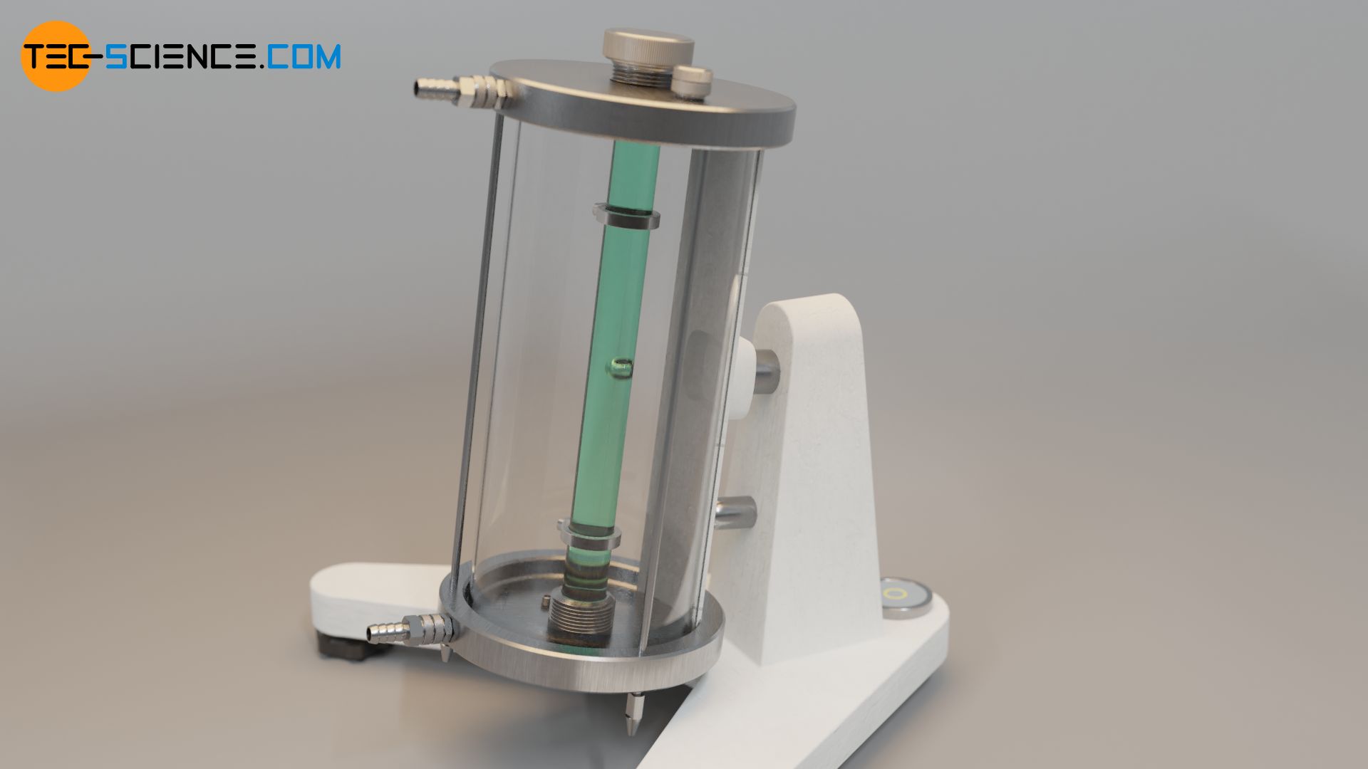 |
| Fig. 01 Modern falling ball viscometer. Notice the that the size of the instrument is too large. |
You may also imagine a different geometrical configuration to perform the mechanical balance so that a different viscometer would be created. Such is the case of the falling cylinder viscometer and the rolling ball viscometer as well, among others.
How does the Stokes viscometer works?
As mentioned earlier, this instrument is based on the mechanical of three different forces acting on a sphere falling through a fluid,
- one due to friction, acting upwards against the falling movement of the ball, which is called: frictional force,
- one due to gravity, acting downwards beacause of the mass of the ball, which is called: gravitational force, and
- another one due to buoyancy, acting upwards because of the smaller fluid density with respect to that of the ball, which is called: buoyant force.
 |
| Fig. 02 Mechanical balance of forces acting on a sphere falling in a fluid. |
At this moment, I am not concerned with the little algebra of the mechanical balance and perhaps in the near future I shall present the demonstration of this but in the meantime hte reader must accept that: from this mechanical balance the dynamic viscosity $\mu$ comes up as,
$\mu = \dfrac{2}{9}\dfrac{r^2 g \left( \rho_s - \rho_f \right)}{v_\infty}$ Eq. (01)
where:
$r$ is the radius of the sphere,
$\rho_s$ is the density of the sphere,
$\rho_f$ is the density of the fluid which viscosity we want to know,
$v_\infty$ is the terminal velocity, and
$g$ is the acceleration due to gravity.
All parameters in the right hand side of Eq. (01) are known or can be determined easily. Perhaps, the most difficult parameter to estimate is the terminal velocity $v_\infty$.
Some comments on the terminal velocity
For short, the terminal velocity is the one to be measured in the viscometer so that careful measurements are required. Therefore, some remarks are given to benefit the experimentalists,
- the terminal velocity is only achieved when no more changes in the magnitude of the velocity are seen. In other words, the terminal velocity $v_\infty$ is that when a constant value is reached,
- at the beginning of the experiment when the ball starts falling velocity is not constant and possibly becomes constant at the end of its trip near the end of the clindrical container,
- in fluids with low viscosity (such as water) the terminal velocity could take a larger distance to be achived in comparison to more viscous fluids (such as gycerine and oils). This means that in some cases longer cylinders could be needed,
- estimation of the terminal velocity requires measurements of time at several places along the cylinder so that $v_\infty$ can be truly known.
 |
| Fig. 03 This sketch shows the real terminal velocity which is achieved by the ball near the end of its trip down the cylinder. |
Experimental pitfalls in the Stokes viscometer
Viscosity measurements in the Stokes viscometer are not as straight as it seem in this old instrument!
Several factors may affect your estimations. Here are some,
- ball and cylinder diameter ration may be important. If the ball and the cylinder have similar diameters the forces due to the cylinder wall proximity may come into play so that viscosity measuremensts would not be correct,
- the Stokes viscometer is best recommended for newtonian fluids or fluids with not strong non-newtontian behavior. For non-newtonian fluids other techniques and instruments have already been developed,
- some Stokes viscometers use optical sensors to detect the presence of the ball and automatically record the time at different places along the cylinder. These sensors are better suited for transparent fluids (such as water) so that even glycerine may introduce sensor malfunctions. You should be aware of the capabilities of the instrument,
- ball properties such as: volume and density, should be known or be carefully previously determined so that experimental error is reduced to velocity measrements if possible.
- you sould remember that this is a very old instrument based on a simple mechanical balance of forces so that viscosity $\mu$ measurements may not match the values reported on the internet.
What to do if viscosity measurements in the Stokes viscometer are not good?
This is not a new question and its answer has been provided time ago. Viscosity $\mu$ measurements in the Stokes viscometer are not exactly the same as those reported in the literature even for the most simple fluids such as water. Why? Well some reasons were presented in the previous section.
Fortunately, this deviation from the reported real values is constant so that all measurements present the same error or some sort of it. Therefore, equations providing a correction to the measured viscosity have been developed. Here is a couple of these.
If you suspect that the error may be due to the ratio between the ball and cylinder diameter, the following equation may be helpful,
$\mu_{real} = \mu_{meas}\left( 1-2.104\dfrac{r}{R}+2.09\dfrac{r^3}{R^3}-0.95\dfrac{r^5}{R^5} \right)$ Eq. (02)
Also, if you suspect that the terminal veocity $v_\infty$ is hardly achieved over the cylinder length, you may also use the following equation,
$\mu_{real}=\dfrac{\mu_{meas}}{\left(1+2.4\dfrac{r}{R}\right)\left( 1+3.3\dfrac{r}{h} \right)}$ Eq. (03)
where $\mu_{real}$ is the corrected viscosity measurement and $\mu_{meas}$ is the experimental value obtained from the Sotkes viscometer. Also $R$, $r$ and $h$ stand for the cylinder radius, the ball radius and the cylinder working height.
- Using the Stokes viscometer
- Up and running with Numerical Recipes in Fortran 90
- Bracketing roots (zbrac) - Numerical Recipes in F90
- An improvement for bracketing roots (zbrak) - Numerical recipes in F90
- The bisection method (rtbis) - Numerical Recipes in F90
- The false position method (rtfls) - Numerical recipes in F90
- The 4th-order Runge-Kutta method for systems of ode in F90
- Dealing with higher order ODE when using the 4th-order Runge-Kutta mehtod
- Boundary value problem by a shooting method - Case #1 Linear interpolation


No comments:
Post a Comment