WARNING
Make sure the whole control station is not energized before touching or starting your exercise!
Objective
Learn the use of an encapsulated relay to keep on an AC bulb light as a guide to connect larger process equipment, such as electrical motors.
Material
Multimeter
AC/DC power supply. Input 120V AC and output 24V DC, 1A (at least)
Push button (green )
Push button (red)
Pilot light (green). 24V DC
Bulb light. AC
Encapsulated relay 24V DC with contacts for 8A 250V
What to do
For this exercise, one of the contacts of the relay shall be used for latching, with 24V DC, and the other one for turning on the bulb light.
Connect the encapsulated relay coil terminals (A1 and A2) after the start button
Connect one of the normally open encapsulated relay contacts (say 24 and 21) in parallel with the start button
In rung 1. Connect the other normally open encapsulated relay contacts (say 14 and 11)
In rung 1. Connect the AC bulb light after the relay contact (14,11)
Set on the power supply
Use the following ladder diagram:
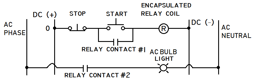 |
| Ladder diagram for turning on/off a bulb by means of an encapsulated relay |
The pilot light should turn on when the start button is pushed and turn off when the stop button is depressed
Check for continuity if needed
How to do it
For this exercise the same setup developed for LE 02 and LE03 are to be used. Details shall be omitted and refer to LE 02 and LE03 for more information.
Step 1. Identification of the encapsulated relay
There are several configurations of encapsulated relays of varying size, mounting, number and type of contacts, for example. The ones used for this exercise are the most common as shown,
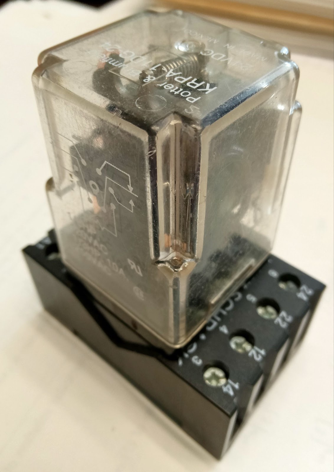 |
| Perspective view of an encapsulated review |
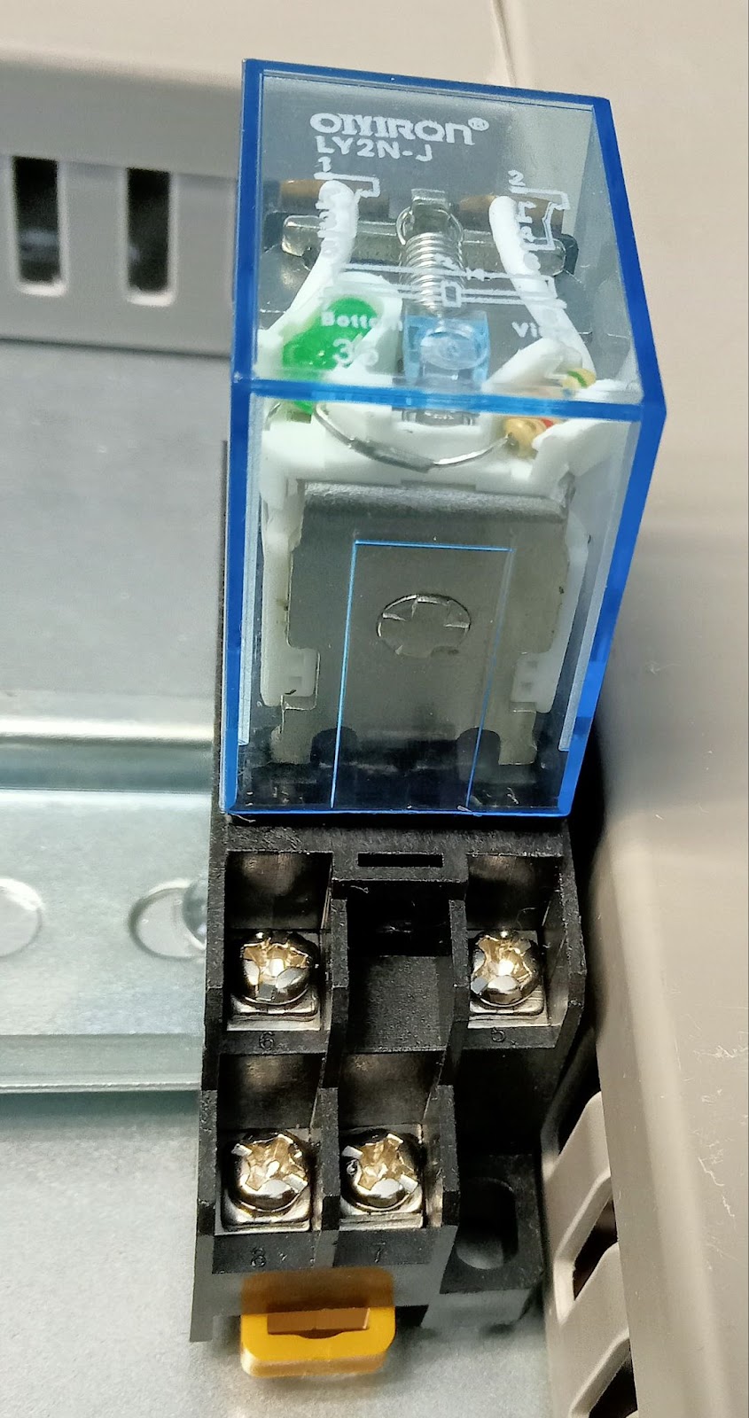 |
| Vew of contacts in an encapsulated relay |
The encapsulated relay have a typical contact configuration as follows,
 |
| Detail of terminal connections in an encapsulated relay |
 |
| Diagrams of connections in an encapsulated relay |
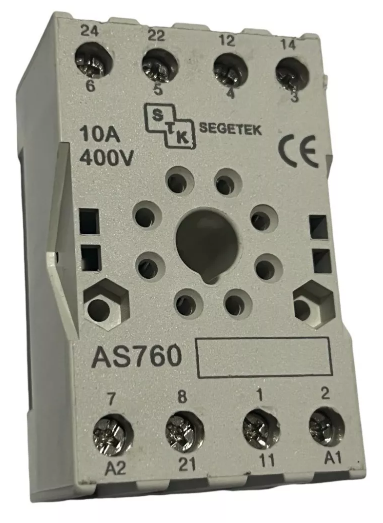 |
| Connection site of an encapsulated relay |
Step 2. AC bulb light connection
As you should know the AC bulb works as the one at your house. One of its terminals goes to the phase (live) wire while the other one to the neutral wire. The one thing you should care about is that this is not connected to the 24V DC blocks but to the AC blocks.
Then, you should connect the bulb as follows. A phase wire from the block should connect to one of the terminals of the NO contact of the relay. From the other contact terminal a wire should connect to one of the terminals of the bulb. Finally, use another wire to connect the other bulb terminal to the neutral block.
Step 3. Energizing the loop
In order to power the loop you should activate the circuit breaker to the ON position with the lever upl and the green indicator being shown.
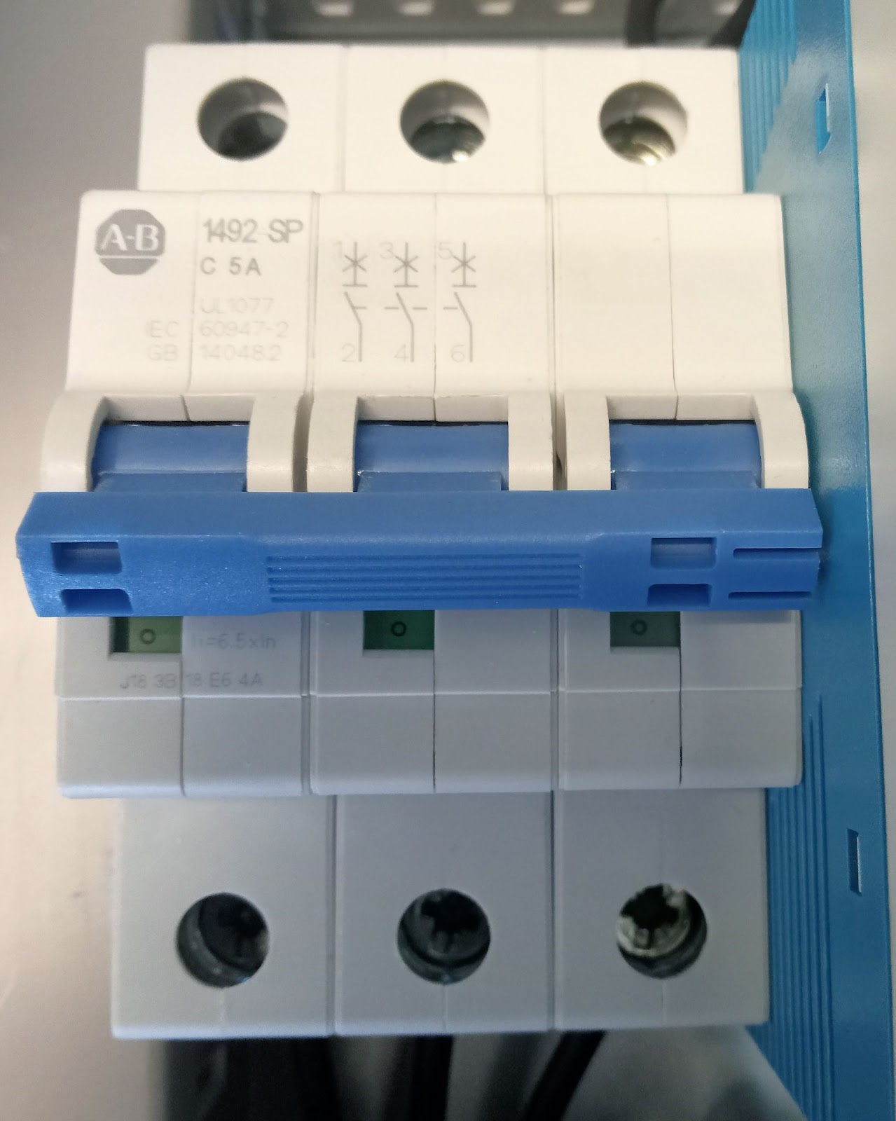 |
| Thermal breaker |
Step 4. Using the buttons
If your connection was right then as the loop was powered, nothing should happen. However, when you push the start button the bulb should turn on and keep in this state. Next, when you push the stop button the bulb should turn off.
Step 5. Continuity and DC voltage test
Check for continuity at every contact and for 24V DC using the multimeter. Since you are using a power source for 24V DC you should get a reading not far from this value.
Continue your training with the next exercise
Any question? Write in the comments and I shall try to help.
Other stuff of interest
- LE01 - AC and DC voltage measurement and continuity test
- LE 02 - Start and stop push button installation 24V DC LE 03 - Turn on/off an 24V DC pilot light with a push button
- About PID controllers
- Ways to control a process
- About pilot lights
- Solving the Colebrook equation
==========
Ildebrando.


No comments:
Post a Comment