ChemEng stuff followers

Showing posts with label Electric motors. Show all posts

Wednesday, February 19, 2025

Mechanical energy added to a fluid - A pump

 An important component of the general mechanical energy equation

$\dfrac{p_1}{\gamma}+z_1+h_A-h_R-h_L+\dfrac{v_1^2}{2g}=\dfrac{p_2}{\gamma}+z_2+\dfrac{v_2^2}{2g}$        Eq. (01)

is $h_A$ since it represents the mechanical energy added to the fluid so that it can continue its trip through the pipe. At this point, two cases are visualized,

  • the energy $h_A$ is one the system requires in order to the pipe system to do its work, and
  • the energy $h_A$ is brought from the technical features of a real life pump, for example, so that the conditions of the pipe system are changed in turn.

Of course, in most technical problems both cases presented above are part of the solution in an iterative procedure.

What is the relationsip between $h_A$ and a pump

Since the pump takes electrical energy and transforms it into mechanical energy to be later transferred into the fluid, these  two parameters should be related. This is done through the effeciency of the motor,

$\mathbf{e_M}=\dfrac{Power\, output\, from \, the\, motor}{Power\, delivered\, by\, fluid}=\dfrac{P_O}{P_R}$    Eq. (02)

where $P_O$ is the mechanical power the motor so that the impeller may turn at certain speed with certain force and $P_R$ is the power the fluid actually receives. Since part of the power $P_O$ is wasted as heat or lost due to wearing of mechanical parts, $P_O>P_R$ and as a consequence $\mathbf{e_M}<1$. If $\mathbf{e_M}=1$ you would have an impossible thermodynamical machine. $P_O$ is a parameter measured and supplied, in the name plate, by pump manufacturers so that this data is easy to get.

Notice that Eq. (02) is the same if instead of a pump the case were that of a turbine (actioned by a mechanical energy of the fluid). We would be talking about $h_R$ instead of $h_A$ too.

For a centrifugal pump the power transferred into the fluid and the energy added $h_A$ are related as follows,

$P_R=h_A\gamma Q$        Eq. (03)

where $Q$ is the volumetric flow rate and $\gamma$ a property of the fluid. Also, from Eq. (03) it is obvious that $P_R$ would be very hard to measured. Therefore, it is more common to speak of the efficiency of a pump which we know is smaller than 1 but with present technological advances could be in the range of 0.8 - 0.9 for new equipments. Then, the usual case would be that $P_R$ is unknown, so that,

$P_R=\mathbf{e_M}P_O$        Eq. (04)

and consequently, Eq. (01) becomes,

$\mathbf{e_M}P_O=h_A\gamma Q$        Eq (05)

From Eq. (05), $h_A$ is isolated to be,

$h_A=\dfrac{\mathbf{e_M}P_O}{\gamma Q}$        Eq. (06)

In this way $h_A$ can only be estimated if the efficiency of the pump $\mathbf{e_M}$ and power of the motor of the pump $P_O$ are known.

Wednesday, November 20, 2024

About the contactor

 For short, a contactor is an encapsulated relay on steroids.

Just as the encapsulated relay, a contactor has:

  • a coil,
  • a set of contacts and
  • a test button.

However, a contactor is built for heavy duty applications.


You can read about the encapsulated relay here: About the encapsulated relay.

Knowing the contactor

A contactor should be easy to identify. You should see coil terminals, auxiliary contacts (NO or NC or a combination of these), power contacts and a small level working as a test button. Depending on the manufacturer and model, these features can be arranged in different ways.

Most models are design for rail mounting inside a cabinet. However, more expensive models may have other features such as small pilot lights or self-coupling to other components such as overload relays, to say an example.

Images of sample contactors


The coil

The contactor coil can be easily identified by the A1 and A2 terminals. You should  remember that depending on the model, the coil may be for DC or AC and design for a given voltage too.

In the contactor, the coil does the same work as the encapsulated relay: when it is energized a set of contacts is open or closed.

The contacts

In the contactor, two types of contacts appear,

  • auxiliary contacts and
  • power contacts.

Auxiliary contacts are meant for turning on/of devices of low voltage such as: pilot lights or alarms, for example. On the other hand, power contacts are used for powering equipment requiring high voltaje and representing a potential danger for an operator, such as: motors or electrical resistances, to name some.

In a contactor, the number of contacts are,obviously, specified according to the application of the component. It is common practice that auxiliary contacts are NO but one NO and one NC or only NC contacts can be looked for. You can identify the auxiliary contacts in the contactor by NO or NC legend.

Contacts in a contactor. Manufacturer: WEG, Model: CWB9


On the other hand, power contacts are always NO since these are meant for energizing an equipment. You can identify the power contacts by the letters L1, L2, etc. and T1, T2, etc.. The letters L and T stand for: line and terminal; while the numbers indicate correspondence between each terminal, this is: L1 and T1 are a NO contact, and so on. Also, all NO power contacts are independent so that L1 and T2 do not form a contact.

Specification of a contactor

Specifying a contactor is usually reduced to determine the number of NO/NC auxiliary and NO power contacts. Therefore, you should, first, determine what is to be turn on/off by the auxiliary contacts so that a ladder diagram needs to be well established before anything else.

The power contacts are related to the power diagram or circuit. You need to know if the equipment is single or triple phase or something else so that the number of poles (NO contacts) can be determined.

Rating

Contactor rating usually refers to the NO power contacts since these are the ones to be subjected to high voltage and current. These contacts need to be such that can withstand a given maximum voltage and current intensity.

Again, you need to know the electrical features of the equipment to plug into the contactor so that you can safely use the proper option.

Sometimes, rating is also related to the selection of the coil. However, the coil is selected according to ladder diagram and features of other components in the same circuit.

Any question? Write in the comments and I shall try to help.

Other stuff of interest

Saturday, February 24, 2024

About the encapsulated relay

 An encapsulated relay is a device used for closing NO contacts or openning NC contacts. These NO or NC contacts can be used for auxiliar or power purposes.

On application of the encapsulated relays is for electric isolation between two circuits. One of these can be potentially dangerous (high voltage) while the other one could be safer for operators (low voltage).

Other applications for encapsulated relays are known, such as: interfacing between actutators and controlling devices, etc.

How does an encapsulated relay looks like?

Well it depends on the model you are referring to. For example you may find some like those sell by ABB,

Fig. 01 ABB encapsulated relays.

Among the features that make these kind of relays we may list,

  • different number of contacts NO/NC are available. You may have one contact only or four or more,
  • there are options for soldering on pcb,
  • other models are suitable for reduce space installation in control panels,
  • other models are design to resist vibrations.
However, one feature all relays in Fig. 01 share is that these can be mounted on rail DIN.

The encapsulated relays are usually made of two parts. The relay module and the socket. The socket is the accesory that allows the relay module to be firmly mounted to the rail DIN.
Fig. 02 Here is an image of an encapsulted relay showing the pins (bottom metal sticks)

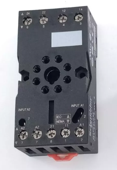
Fig. 03 Socket of an encapsulated relay. Notice that the terminals are numbered and are related to the pin and diagram of the encapsulated relay. These may change from one manufacturer to other.


How does an encapsulated relay work?

In order to give a more precise explanation we should refer to the diagram of an encapsulated relay. Take for instance the one shown below,
Fig. 04 Diagram of and 8-pin encapsulated relay. Numbers in parenthesis are related to the pin of the relay while numbers without parenthesis are related to contact numbers in the socket (see Fig. 03).

Contacts are formed with the terminals available. For example, in Fig. 03 terminals 24 and 21 are a normally open contact NO while 21 and 22 make a normally closed contact NC. As you can see, the encapsulated relay in Fig. 04 has two NO contacts and two NC contacts.

Terminals A1 and A2 are devoted to the coil of the relay. As electricity passes through it the coil is energized and an electromagnet is formed. As the electromagnet is formed the contacts change their position. This is, the NC contacts open and the NO contacts close.

Then, you may use low voltage to operate the relay coil and the contacts for higher voltage so that you are using the encapsulated relay to isolate two different circuits. This is why this device can be considered for safety when designing a control loop.


Monday, January 1, 2024

On the estimation of the power consumption of an electric motor

This is a bit technical engineering stuff but I hope this could be a good reference for you.

Some features of electric motors

Industrial electric motors can be classified, for example, as,

  • as being built to work with alternate or direct current, and
  • as being built to work with just a single phase or three phases.
This information is provided by the manufacturer in the motor name plate as shown in Fig. 1.

Fig. 1 Electric motor nameplate with key data for power consumption estimations

In other cases, the information is not available because the equipment has not been bought yet! Fortunately, some manufacturers have made available datasheets of its equipments on their official internet site. This usually occurs when a process plant is the design stage but this info shall be paramount for energy operation costs estimations.

A third important case occurs when the electric motor is already installed, has been working for a long period (years, may be) and its namplate rated features may be different from its actual operating conditions. In this case power consumption has to be measured in the motor directly.

From here on we will focuse on AC motors only since the calculation for DC motors is barely the same for single phase AC motors.

Some details on power consumption estimations

As you may see, power in the motor nameplate is usually given in hp (horse power) as shown in Fig. 1 above. For cost of power consumption the unit for power of common use all over the world is: kW h (kilo Watts per hour).

Next, if the power data is in hp, just use the following conversion factor to get kW:

$\dfrac{1\; hp}{0.7457 \; kW}$

It is not obvious but the power provided in the nameplate is given per hour. In other words, what you see in the nameplate is in fact: kW h. This can be confusing but take it as it is.

Another element you should not forget is the motor efficiency. Efficiency is different in several conditions:
  • if the motor is new or not,
  • if proper maintenance has been performed,
  • the design of the motor (for example, squirrel cage is a type of design),
  • according to the load conditions,
  • if it is a high efficiency (and more expensive) motor or not.
For short, the efficiency of an electric motor shall lye between 70 and 90% according to a combination of factors as those listed above. The less efficient a motor is, the more energy this one will need to develop the work. In other words, an electric motor with low efficiency will in fact need more kW h than those specified in the nameplate.

A final comment. Power consumption for single or three phases motors is different.

Most popular posts