An encapsulated relay is a device used for closing NO contacts or openning NC contacts. These NO or NC contacts can be used for auxiliar or power purposes.
On application of the encapsulated relays is for electric isolation between two circuits. One of these can be potentially dangerous (high voltage) while the other one could be safer for operators (low voltage).
Other applications for encapsulated relays are known, such as: interfacing between actutators and controlling devices, etc.
How does an encapsulated relay looks like?
Well it depends on the model you are referring to. For example you may find some like those sell by ABB,
 |
| Fig. 01 ABB encapsulated relays. |
Among the features that make these kind of relays we may list,
- different number of contacts NO/NC are available. You may have one contact only or four or more,
- there are options for soldering on pcb,
- other models are suitable for reduce space installation in control panels,
- other models are design to resist vibrations.
However, one feature all relays in Fig. 01 share is that these can be mounted on rail DIN.
The encapsulated relays are usually made of two parts. The relay module and the socket. The socket is the accesory that allows the relay module to be firmly mounted to the rail DIN.
 |
| Fig. 02 Here is an image of an encapsulted relay showing the pins (bottom metal sticks) |
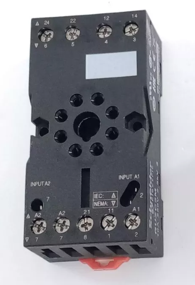 |
| Fig. 03 Socket of an encapsulated relay. Notice that the terminals are numbered and are related to the pin and diagram of the encapsulated relay. These may change from one manufacturer to other. |
How does an encapsulated relay work?
In order to give a more precise explanation we should refer to the diagram of an encapsulated relay. Take for instance the one shown below,
 |
| Fig. 04 Diagram of and 8-pin encapsulated relay. Numbers in parenthesis are related to the pin of the relay while numbers without parenthesis are related to contact numbers in the socket (see Fig. 03). |
Contacts are formed with the terminals available. For example, in Fig. 03 terminals 24 and 21 are a normally open contact NO while 21 and 22 make a normally closed contact NC. As you can see, the encapsulated relay in Fig. 04 has two NO contacts and two NC contacts.
Terminals A1 and A2 are devoted to the coil of the relay. As electricity passes through it the coil is energized and an electromagnet is formed. As the electromagnet is formed the contacts change their position. This is, the NC contacts open and the NO contacts close.
Then, you may use low voltage to operate the relay coil and the contacts for higher voltage so that you are using the encapsulated relay to isolate two different circuits. This is why this device can be considered for safety when designing a control loop.
 |
| Fig. 05 Energizing an encapsulated relay |
Any question? Write in the comments and I shall try to help.
Other stuff of interest
- LE01 - AC and DC voltage measurement and continuity test
- LE 02 - Start and stop push button installation 24V DC
- Some examples of temperature instruments
- Minor losses - Formulas
- What is a process variable?
- What are the most important process variables?
- Time dependence of process variables
- A list of process variables
Ildebrando.

No comments:
Post a Comment