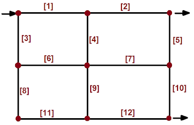
The main idea behind the Hardy-Cross method is to force a head loss $h_L$ balance among all pipes that are part of a flow loop. Without the $h_L$ balance flow rates, which are usually the unknown, they cannot be determined. There are other methods, but this is the most familiar.
This methodology, as you may already know, is based on the general equation for mechanical energy balance, so that every loop in the above network must be decomposed into smaller parts, which are in fact the pipe sections.
Note: A loop is a circuit of flow. In other words, a loop is formed by interconnected pipe sections through which the fluid may travel in a given direction. For example, pipe sections [1], [4], [6], and [3] form a loop.
Then, for any of the 12 pipe sections in the network above, a particular head loss is defined as follows,
$h_L^{(n)}=f_F^{(n)}\frac{L_n}{D_n}\frac{v_n^2}{2g}$ Eq. (1)
Other stuff of interest
- LE01 - AC and DC voltage measurement and continuity test
- LE 02 - Start and stop push button installation 24V DC
- LE 03 - Turn on/off an 24V DC pilot light with a push button
- LE 04 - Latch contact with encapsulated relay for turning on/off an AC bulb light
- LE 05 - Emergency stop button installation
- About PID controllers
- Ways to control a process
- About pilot lights
- Solving the Colebrook equation
- Example #01: single stage chemical evaporator
- Example #02: single stage process plant evaporator
- Example #03: single stage chemical evaporator
- Example #04: triple effect chemical evaporator
- Gas absorption - General comments
- Equilibrium diagrams from gas component solubility data
- Distillation - General comments
==========
Ildebrando.


No comments:
Post a Comment