ChemEng stuff followers

Showing posts with label control loop. Show all posts

Wednesday, November 20, 2024

About the contactor

 For short, a contactor is an encapsulated relay on steroids.

Just as the encapsulated relay, a contactor has:

  • a coil,
  • a set of contacts and
  • a test button.

However, a contactor is built for heavy duty applications.


You can read about the encapsulated relay here: About the encapsulated relay.

Knowing the contactor

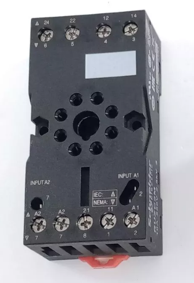
A contactor should be easy to identify. You should see coil terminals, auxiliary contacts (NO or NC or a combination of these), power contacts and a small level working as a test button. Depending on the manufacturer and model, these features can be arranged in different ways.

Most models are design for rail mounting inside a cabinet. However, more expensive models may have other features such as small pilot lights or self-coupling to other components such as overload relays, to say an example.

Images of sample contactors


The coil

The contactor coil can be easily identified by the A1 and A2 terminals. You should  remember that depending on the model, the coil may be for DC or AC and design for a given voltage too.

In the contactor, the coil does the same work as the encapsulated relay: when it is energized a set of contacts is open or closed.

The contacts

In the contactor, two types of contacts appear,

  • auxiliary contacts and
  • power contacts.

Auxiliary contacts are meant for turning on/of devices of low voltage such as: pilot lights or alarms, for example. On the other hand, power contacts are used for powering equipment requiring high voltaje and representing a potential danger for an operator, such as: motors or electrical resistances, to name some.

In a contactor, the number of contacts are,obviously, specified according to the application of the component. It is common practice that auxiliary contacts are NO but one NO and one NC or only NC contacts can be looked for. You can identify the auxiliary contacts in the contactor by NO or NC legend.

Contacts in a contactor. Manufacturer: WEG, Model: CWB9


On the other hand, power contacts are always NO since these are meant for energizing an equipment. You can identify the power contacts by the letters L1, L2, etc. and T1, T2, etc.. The letters L and T stand for: line and terminal; while the numbers indicate correspondence between each terminal, this is: L1 and T1 are a NO contact, and so on. Also, all NO power contacts are independent so that L1 and T2 do not form a contact.

Specification of a contactor

Specifying a contactor is usually reduced to determine the number of NO/NC auxiliary and NO power contacts. Therefore, you should, first, determine what is to be turn on/off by the auxiliary contacts so that a ladder diagram needs to be well established before anything else.

The power contacts are related to the power diagram or circuit. You need to know if the equipment is single or triple phase or something else so that the number of poles (NO contacts) can be determined.

Rating

Contactor rating usually refers to the NO power contacts since these are the ones to be subjected to high voltage and current. These contacts need to be such that can withstand a given maximum voltage and current intensity.

Again, you need to know the electrical features of the equipment to plug into the contactor so that you can safely use the proper option.

Sometimes, rating is also related to the selection of the coil. However, the coil is selected according to ladder diagram and features of other components in the same circuit.

Any question? Write in the comments and I shall try to help.

Other stuff of interest

Saturday, February 24, 2024

About the encapsulated relay

 An encapsulated relay is a device used for closing NO contacts or openning NC contacts. These NO or NC contacts can be used for auxiliar or power purposes.

On application of the encapsulated relays is for electric isolation between two circuits. One of these can be potentially dangerous (high voltage) while the other one could be safer for operators (low voltage).

Other applications for encapsulated relays are known, such as: interfacing between actutators and controlling devices, etc.

How does an encapsulated relay looks like?

Well it depends on the model you are referring to. For example you may find some like those sell by ABB,

Fig. 01 ABB encapsulated relays.

Among the features that make these kind of relays we may list,

  • different number of contacts NO/NC are available. You may have one contact only or four or more,
  • there are options for soldering on pcb,
  • other models are suitable for reduce space installation in control panels,
  • other models are design to resist vibrations.
However, one feature all relays in Fig. 01 share is that these can be mounted on rail DIN.

The encapsulated relays are usually made of two parts. The relay module and the socket. The socket is the accesory that allows the relay module to be firmly mounted to the rail DIN.
Fig. 02 Here is an image of an encapsulted relay showing the pins (bottom metal sticks)

Fig. 03 Socket of an encapsulated relay. Notice that the terminals are numbered and are related to the pin and diagram of the encapsulated relay. These may change from one manufacturer to other.


How does an encapsulated relay work?

In order to give a more precise explanation we should refer to the diagram of an encapsulated relay. Take for instance the one shown below,
Fig. 04 Diagram of and 8-pin encapsulated relay. Numbers in parenthesis are related to the pin of the relay while numbers without parenthesis are related to contact numbers in the socket (see Fig. 03).

Contacts are formed with the terminals available. For example, in Fig. 03 terminals 24 and 21 are a normally open contact NO while 21 and 22 make a normally closed contact NC. As you can see, the encapsulated relay in Fig. 04 has two NO contacts and two NC contacts.

Terminals A1 and A2 are devoted to the coil of the relay. As electricity passes through it the coil is energized and an electromagnet is formed. As the electromagnet is formed the contacts change their position. This is, the NC contacts open and the NO contacts close.

Then, you may use low voltage to operate the relay coil and the contacts for higher voltage so that you are using the encapsulated relay to isolate two different circuits. This is why this device can be considered for safety when designing a control loop.


Sunday, January 28, 2024

Two types of instruments for control loops

When selecting an instrument for a given control loop you need, first, to know how these devices actually work.

See the post Does it matter to know how an instrument works? for further reference.

However, in a general way you also need to know general classifications of some instruments available in the market. Here is an important classification you may start with.

Analog vs electronic instruments


Instruments according to its technoloy

  • analog/mechanical instruments
  • electronic instruments
Of course there are other options we could name as a category not included in oir list but these can be better considered as sub-categories of those major categories. Here is a short explanations of this.

Analog/mechanical instruments

These are devices that are purely mechanical and are tipically old (or mature) technologies. Examples of these instruments are:


  • the Bourdon manometer,
  • the bulb thermometer,
  • the glass level meter, 
  • etc.
Some features of these instruments may also be listed
  • do not need electricity or batteries to work,
  • since these are mature technologies, there are many low cost options,
  • depend on a human for reading measurements,
  • have poor precision since engraved/printed scalings have some limitations,
  • closed control loops are not always possible with these instruments.

Electronic instruments

These type of instruments have some advantages over analog/mechanical technologies. Examples of these are
  • pressure transducers,
  • thermocouples,
  • infrared thermometers,
  • pH meters,
  • ultrasonic flow meters,
  • etc.
As you may notice from the above list, technologies such as: optical, magnetic, ultrasonic, etc. are all placed under the electronic instruments category.

These instruments provide in fact improvements of the analog/mechanical options. Some of its features are
  • are preferred for closed loop possibilities,
  • are more precised than analog/mechanical options,
  • need power input or batteries,
  • do not depend on a human for measurements (its measurements are automated),
  • installation may not be easy,

Tuesday, August 8, 2023

What are the most common colors for pilot lights?

The main purpose of pilot lights is to serve as indicators of the current status of some device or equipment or process. An alternate function, and not less important, of pilot lights is concerned with safety. According to the NFPA (National Fire Protection Association) a pilot light gives an indication to attract the operator's attention or to indicate that a certain should be performed

Color code for pilot lights


Most common types of pilot lights

The most common pilot light colors, as related to control panels, are:

  • green pilot lights indicate that an equipment has been turned-on or started or that its operation is normal. The same applies for a control circuit. It would also indicate a safe status as related to the operator's safety. In this case green pilot lights are commonly used;
  • red pilot lights indicate that an equipment has been turned-off or stopped due to a failure. About a control circuit it would indicate an emergency, due to a failure for example. In could also be used to indicate a situation of danger to the operator;
  • yellow pilot lights indicate an abnormal operation of an equipment but not necessarily that it is turned-off. These color light may also be understood as visual an alarm for warning.
Pilot lights


Any question? Write in the comments and I shall try to help.

Other stuff of interest

==========

Ildebrando.

Tuesday, July 4, 2023

About the PID controller

 For short, it is an electronic device capable of controlling a process variable such as temperature or pressure, for example.

A little of technical background

The origin of PID controllers is on the well known mathematical expression:

$CO(t) = Bias - K\left[SP-PV(t)\right] - \dfrac{K}{t_i}\int_0^{\tau=t} \left[SP-PV(\tau)\right] \; d\tau - K t_d \dfrac{d}{t}\left[ SP-PV(t) \right]$        Eq. (01)

where $CO(t)$ stands for the controller output, $Bias$ for the situation at which the measured process variable equals the set point, $SP$ for the constant set point, $PV(t)$ for the measurements of the time dependent process variable, $K$ for the controller gain, $t_i$ for the integral time and $t_d$ for the derivative time. Equation (01) deserves a more detrailed explanation but it is leaved for another post.

For now, it should be sufficient to say that $CO$ is in fact a signal that is to be used to modulate the operation the final element of control, say a valve or motor, for example. From the practical point of view, Eq. (01), if applied to any process variables, should be enough to keep a process variable as close as possible to its set point (there are some further details to discuss for this assumption so that this is not always true).

The real PID controller

In practice what you have is a device following the rule established in Eq. (01) along with a number of problems and technical solutions already available in the market. It is not clear for the undergraduate student that in real life control situations you would need for example:

  • measure temperature with a thermocouple, an RTD or a infrared sensor,
  • register the process variable data,
  • create a ramp for the process variable,
  • probably use On/Off instead of PID,
  • control pressure instead of temperature,
  • among other things.
Other details would have to be listed above but the point is that implementation of a PID control requires technical details not available in Eq. (01). Then it should not be strange that a real life PID controller could have different presentations and different prices. Take a look to the following examples:
Fig. 1 PID controllers

Some of the above shown will fit for particular applications and budgets. The features of these controllers examples may differ according to the brand and not all would be classified as PID controllers but as thermostats.

Perhaps, the most common PID controller is related to temperature as the process variables and its operation/installation/usage would be suitable for thermal applications. However, PID control may also be used for other process variables such as pressure or flow rate which would introduce different technical issues.

Fig. 2 Schematics of how to wire a PID controller

Technicalities

Using a PID controller requires more than just knowing Eq. (01) but knowing about sensors and electricity. As shown in Fig. 2, controlling temperature, for example and accoirding to the controller in Fig. 2, requires to choose between two possible sensors: thermocouples and RTD's; and to adjust the electrical supply to alternate current between 110 to 240 V so that the controller could be powered. We may go further since a particular probe for the sensor would be needed!


PID controller installation/selection would also lead to another disjunctive. Panel mounted versus rail DIN installation. At first this is important from the point of view of available space but it intrinsically means plannification before buying a possibly expensive control device.

Fig. 3 Rail DIN installation of a PID controller

There are many other PID controller models available in the market and it would be difficult to mention all of these. The most important conclusion of this post would be need to understand how to translate the physics behind Eq. (01) into the usage of devices in Figs. 1-3 in order to control a process variable.

Theoretical understanding of Eq. (01) is very important but for the practicing engineer technical knowledge must be added.

Any question? Write in the comments and I shall try to help.

==========
Ildebrando.


Sunday, May 28, 2023

Ways to control a process (or equipment)

This is a tricky, ambiguous, question. One may say that a process or equipment can be controlled only in two different ways:

  • manually or
  • automated.
Since automated control means fully automated, a combination of manual-automated control possibility is  out of question. This also gives origin to two well nown concepts: open loop (lazo abierto) and closed loop (lazo cerrado).

However, the question posed as title of this post goes further. 

How can you implement the manual or automated control of a given process or equipment? 

The shortest answer is a list of options that actually unfolds into further options! There are two well known main categories of control:

  • feedback, and
  • feedforward.
Now, if you go a little deeper another subcategory is found. These options are:

  • On/Off control (control todo o nada)
  • PID control
  • Robust control (control robusto)
  • Fuzzy logic control (control con lógica difusa)
  • Artificial inteligence (inteligencia artificial)

with the last 4 applying for closed loop only. A more detailed study of the previous categories will show that there is still another set of sub-sub-categories. These are perhaps the ones being closer to the technical implementation of the control loop. These are:

  • cascade control (control en cascada)
  • ratio control
From this sort of classification the, novice, engineer or technician may select the features of its control loop and then defining the elements that will make the job. This is in fact an iterative procedure.

Any question? Write in the comments and I shall try to help.

=========
Ildebrando.

Most popular posts