For short, it is an electronic device capable of controlling a process variable such as temperature or pressure, for example.
A little of technical background
The origin of PID controllers is on the well known mathematical expression:
$CO(t) = Bias - K\left[SP-PV(t)\right] - \dfrac{K}{t_i}\int_0^{\tau=t} \left[SP-PV(\tau)\right] \; d\tau - K t_d \dfrac{d}{t}\left[ SP-PV(t) \right]$ Eq. (01)where $CO(t)$ stands for the controller output, $Bias$ for the situation at which the measured process variable equals the set point, $SP$ for the constant set point, $PV(t)$ for the measurements of the time dependent process variable, $K$ for the controller gain, $t_i$ for the integral time and $t_d$ for the derivative time. Equation (01) deserves a more detrailed explanation but it is leaved for another post.
For now, it should be sufficient to say that $CO$ is in fact a signal that is to be used to modulate the operation the final element of control, say a valve or motor, for example. From the practical point of view, Eq. (01), if applied to any process variables, should be enough to keep a process variable as close as possible to its set point (there are some further details to discuss for this assumption so that this is not always true).
The real PID controller
In practice what you have is a device following the rule established in Eq. (01) along with a number of problems and technical solutions already available in the market. It is not clear for the undergraduate student that in real life control situations you would need for example:
- measure temperature with a thermocouple, an RTD or a infrared sensor,
- register the process variable data,
- create a ramp for the process variable,
- probably use On/Off instead of PID,
- control pressure instead of temperature,
- among other things.
Other details would have to be listed above but the point is that implementation of a PID control requires technical details not available in Eq. (01). Then it should not be strange that a real life PID controller could have different presentations and different prices. Take a look to the following examples:
Some of the above shown will fit for particular applications and budgets. The features of these controllers examples may differ according to the brand and not all would be classified as PID controllers but as thermostats.
Perhaps, the most common PID controller is related to temperature as the process variables and its operation/installation/usage would be suitable for thermal applications. However, PID control may also be used for other process variables such as pressure or flow rate which would introduce different technical issues.
Technicalities
Using a PID controller requires more than just knowing Eq. (01) but knowing about sensors and electricity. As shown in Fig. 2, controlling temperature, for example and accoirding to the controller in Fig. 2, requires to choose between two possible sensors: thermocouples and RTD's; and to adjust the electrical supply to alternate current between 110 to 240 V so that the controller could be powered. We may go further since a particular probe for the sensor would be needed!
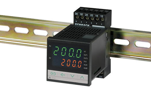
PID controller installation/selection would also lead to another disjunctive. Panel mounted versus rail DIN installation. At first this is important from the point of view of available space but it intrinsically means plannification before buying a possibly expensive control device.
 |
| Fig. 3 Rail DIN installation of a PID controller |
There are many other PID controller models available in the market and it would be difficult to mention all of these. The most important conclusion of this post would be need to understand how to translate the physics behind Eq. (01) into the usage of devices in Figs. 1-3 in order to control a process variable.
Theoretical understanding of Eq. (01) is very important but for the practicing engineer technical knowledge must be added.
Any question? Write in the comments and I shall try to help.
==========
Ildebrando.


No comments:
Post a Comment