WARNING
Make sure the whole control station is not energized before touching or starting your exercise!
Objectives
Learn how to wire pushable buttons for start and stop a 24V DC control loop and to identify electrical open and closed contact symbols.
Material
Multimeter
AC/DC power supply. Input 120V AC and output 24V DC, 1A (at least)
Push button (green )
Push button (red)
What to do
Connect the NC contact of the red button in series with the NO contact of the green button
Set on the power supply
Use the multimeter to test for continuity
Use the multimeter to check for 24V DC at the stop button contacts
Use the following ladder diagram:
 | |
|
How to do it
Step 1.Identify the contacts in each button
Carefully inspect the red and green buttons. These should have a pair of contacts corresponding to NO and NC, which should look as shown in the ladder diagram above.
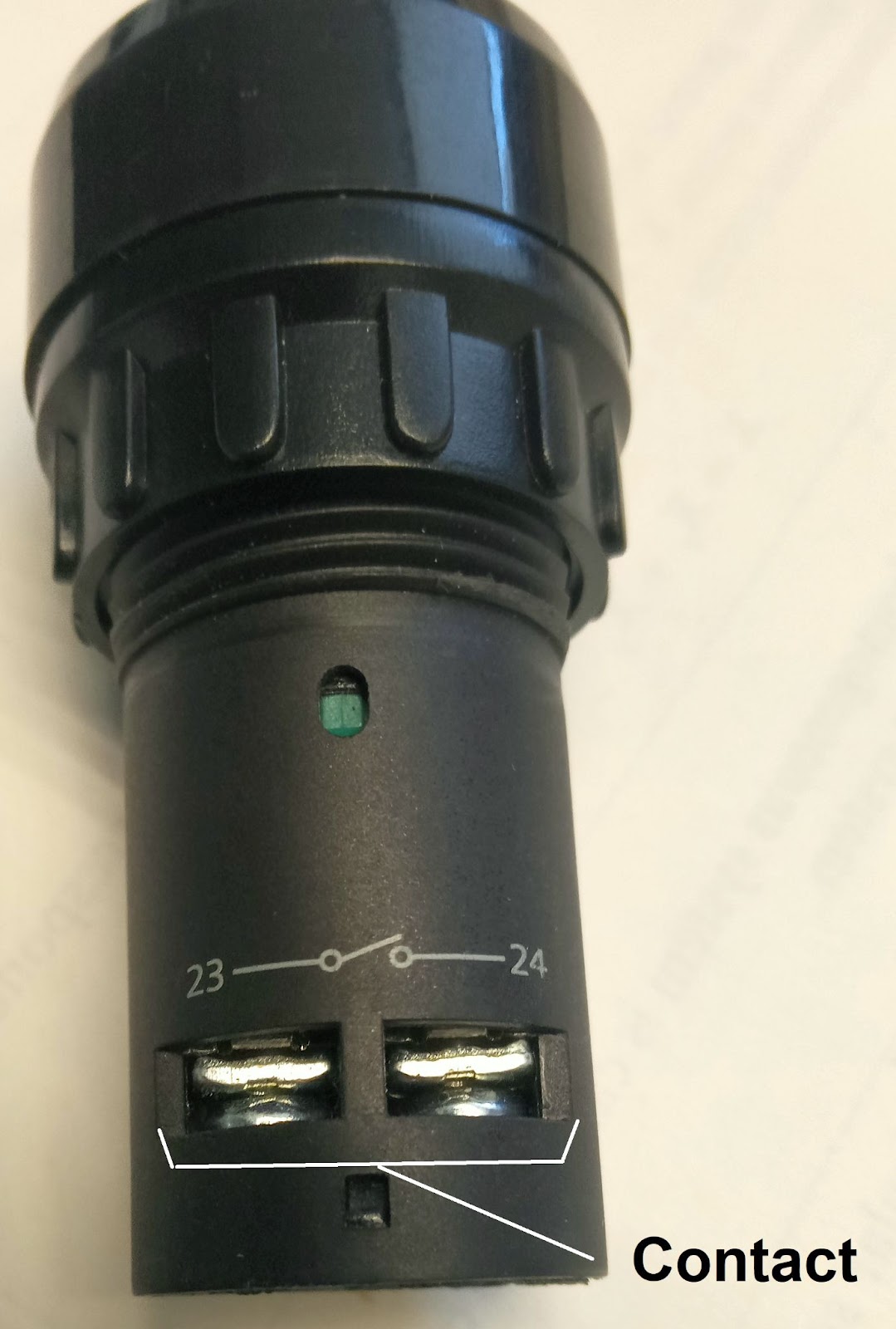 |
NO contact in push botton |
 |
NC contact in push button |
Step 2. DC electricity from the blocks
Take a wire from the corresponding DC (+) terminal blocks, using the corresponding wire color, to connect the stop and start buttons. Use a different wire color to connect the final start button contact with the DC (-) terminal blocks.
 |
| Terminals block for direct current (DC) |
In order to keep everything in order and to ease checking for faults, it is recommended to use brown color wires for DC(+) and blue wires for DC(-), as much as possible.
Step3. Connection of buttons
Follow the ladder diagram above to connect the buttons. Remember that the STOP button corresponds to the NC contact while the START button corresponds to the NO contact. For this case, use the terminal numbers in the contacts as a guide,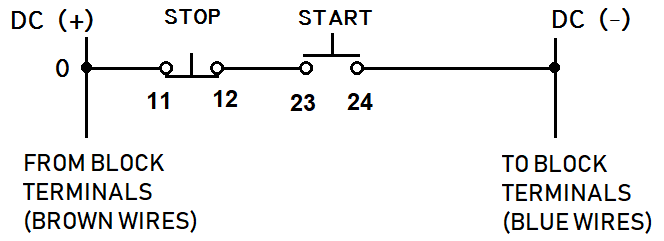 |
| Numbered ladder diagram for start/stop push buttons |
Step 4. Energizing the loop
In order to power the loop you should activate the circuit breaker to the ON position with the lever upl and the green indicator being shown.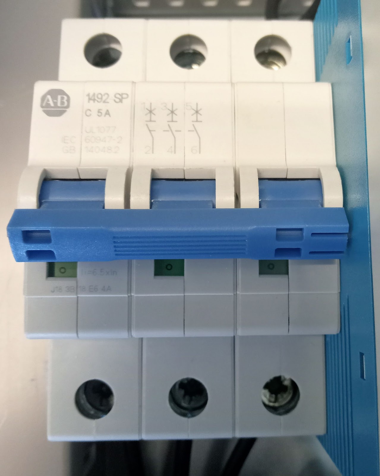 |
| Thermal ciruit breaker |
Step 5. Continuity and DC voltage test
Check for continuity at every contact and for 24V DC using the multimeter. Since you are using a power source for 24V DC you should get a reading not far from this value.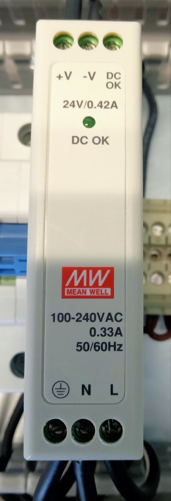 |
| AC/DC converter or power source |
When the STOP button is pushed 24V DC should be read in the multimeter.


No comments:
Post a Comment